
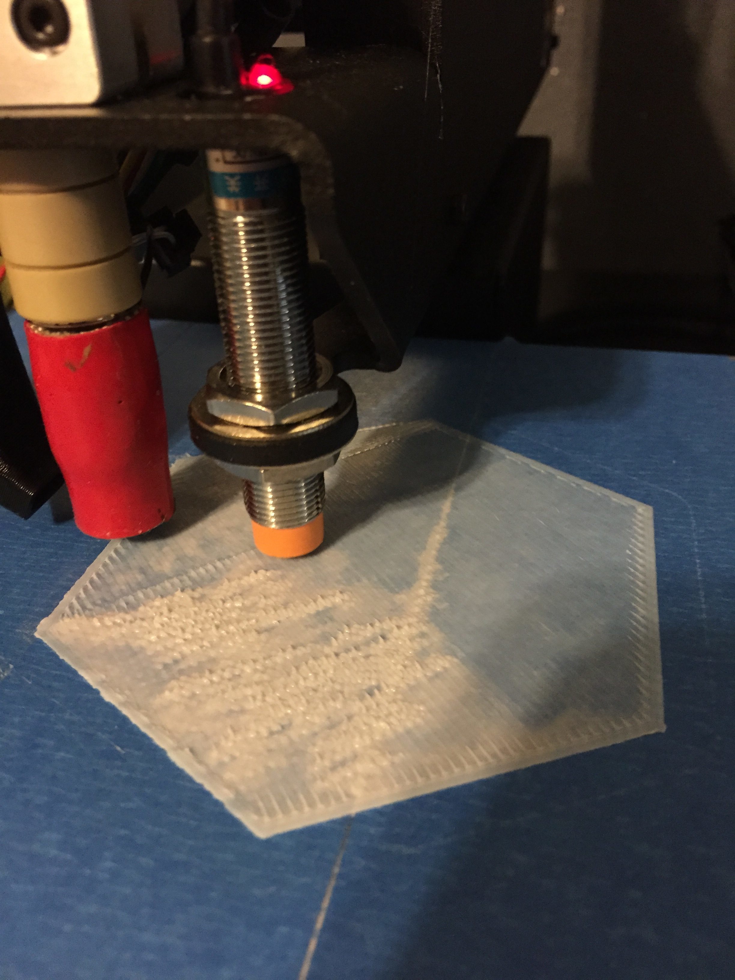
Bad first layer.
Getting a good first layer is paramount to having a successful 3d print. If your nozzle is too close to the board, your filament can either get clogged, it can push around filament that has already been laid down, or it can even damage your bed by gouging it. Having a flat, level bed helps you ensure that your nozzle is a consistent and predictable distance away from your print bed. However, materials for hobby-level 3d printers are never perfect. For example, a MIC 6 aluminum bed is generally pretty flat, but it’s tolerances for flatness still range from .1mm to .38mm (depending on sheet thickness). If you’re printing with layers of .2mm then your bed flatness could vary anywhere from half a layer, up to almost 2 layers. That can have a huge impact on the success of your print.
Levelness vs Flatness
It’s easy to get bed flatness and levelness mixed up, so I’ll run through it briefly. A level bed will be where the two endpoints of the bed connect on a plane that is parallel to the motion system that works with/against it. Both lines ab and cd are technically level, however on line cd you can see that there is not a straight line that connects the end points. Even though c and d can have a level plane drawn between them, the actual line that connects them has variance to it. Make line cd in to a three dimensional surface and you have a good picture of how print beds are actually shaped. 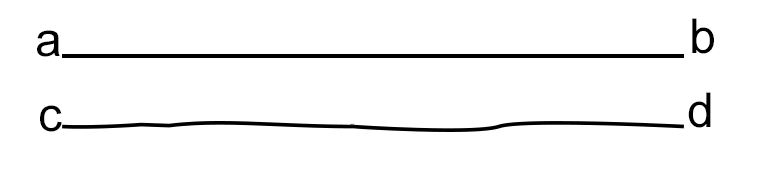 The 3d printing community has come up with several techniques to try to ensure that a printer doesn’t have to have a perfectly flat, perfectly level surface. The first, and most common, technique is auto tramming or auto leveling. This technique surveys 3 corners of your bed and creates a plane from them which is then used to adjust the Z axis during linear movements. The downside of auto tramming is that it assumes that your bed is perfectly flat. Given that this isn’t the case, your auto-trammed bed is still likely to have some localized high or low spots. Auto tramming’s big brother is mesh bed leveling, which seeks to take samples of the bed’s height across many different points on the bed’s surface. Being able to dynamically adjust the Z height across a surface has huge potential for ensuring a good first layer, but it’s not a common implementation yet. Josef Prusa has broken ground on the implementation of mesh leveling, but it hasn’t caught on widely yet and isn’t very easy to implement in other printers due to the technology that’s required to be embedded into the print bed.
How Flat is My Bed?
I came across this issue while trying to print a set of 3D Settlers of Catan pieces. Printing one piece at a time induces a ton of extra work administering each print (the base set and the 5-6 player expansion combine to require 36 pieces for the game board, and this doesn’t include the border pieces), so I was looking to print more pieces for each job. Getting consistency across the entire surface of my bed was causing me trouble, so I made printtools3d to generate Gcode and plot the results as copied from my Octoprint terminal. Here’s some images of how unlevel my bed was under different circumstances:


Looking at those pictures really makes you wonder how anything was able to be printed.
Using printtools3d
The main focus of printtools3d is to provide you with a suite of functions to help visualize the state of your bed. You can start of by using blgcode(x, y), where x and y are the dimensions of your bed in millimeters, to generate gcode for your printer to test the height of a grid of points on your bed. You then upload your gcode to your printer and start the job. You’ll need to copy the output of your terminal (I’ve only tested this with Octoprint) for all of the probings and save it as DirtyData.txt in your working directory. You can then use importBed() to pull in that file and xyztogrid() to convert that bed information into a graph-friendly matrix. Finally, you can use graphBed() to get a visual of your bed.
You can use this visualization in a variety of ways. One way I’ve made use of the graph is to prioritize placement of put smaller pieces in areas of the bed that are flatter. I’ve also used it to determine that the tolerances of my bed aren’t acceptable and to get a new print bed (though I wanted a new one in order to have a larger print surface anyways).
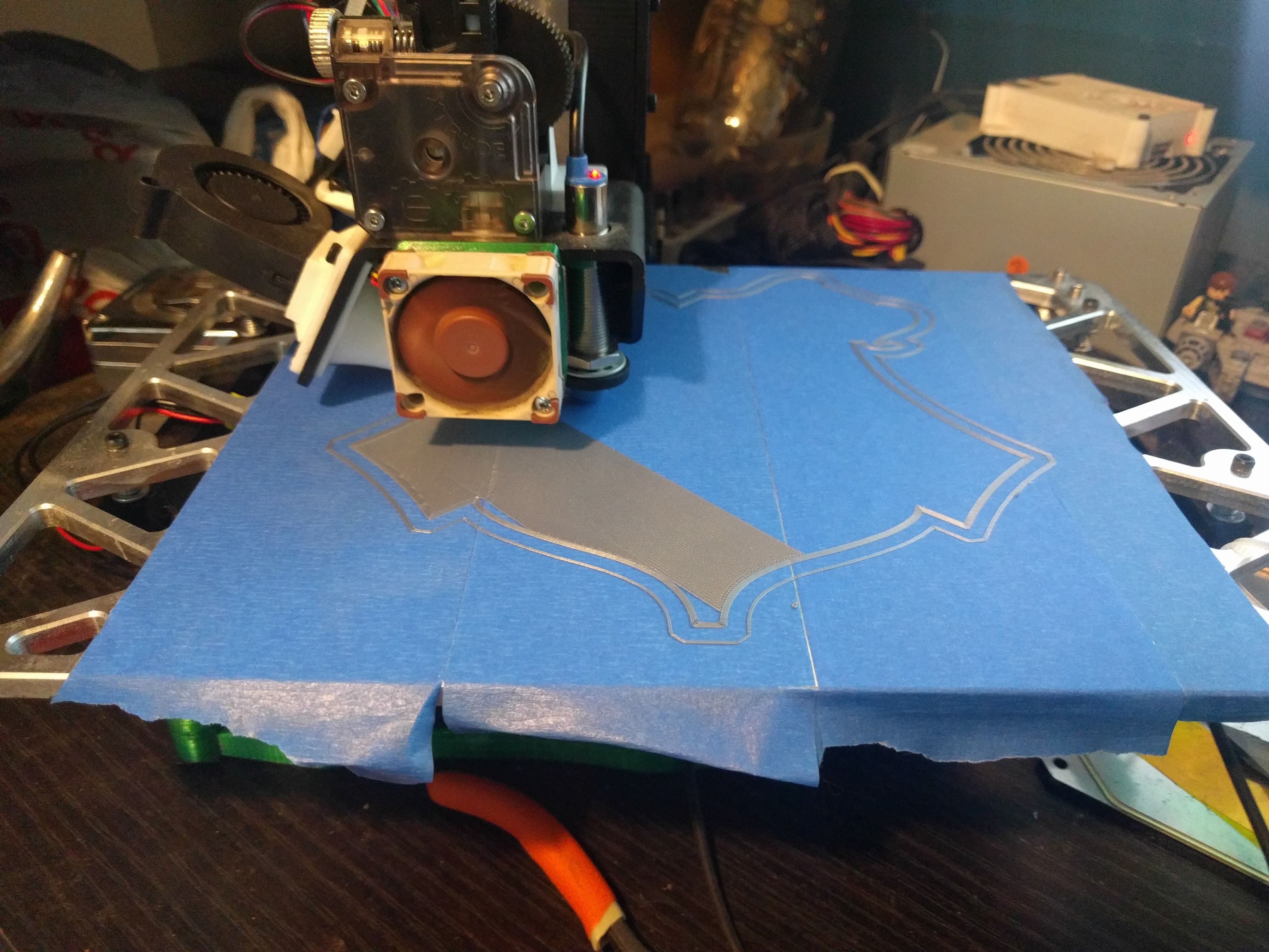
A much cleaner first layer.
Room for Improvement
The current iteration of printtools3d has a ton of room for improvement. It was originally written as a final project for my first class on R (and featured on my professor’s personal site), but I think that the functions aren’t written that well. Additionally, the usage of writing objects to environments isn’t very good R design. I probably knew it at the time of writing the original code, but I was more concerned with getting the project done than having spectacular design choices. Functionally, there is an issue with iterative G28 commands. G28 is a command that tells your printer to send your inductive probe to the bed to see where it’s at, then it pulls the probe up a set amount. this means that the reference Z height is different and dependant on how high or low the bed is, so the graph isn’t an extremely accurate representation of your bed state. This also causes an issue if there is a very unflat/unlevel part of your bed. If the change in vertical height on your bed is greater than the distance that the G28 command pulls the probe up, then your nozzle can crash into your bed. Obviously, this isn’t the kind of results that one would expect from a tool that’s supposed to help you level your bed, so it needs a solution. The first, slowest, and least cool method would be to pick one spot on your bed, either the middle or have your probe search for the highest spot, then use that as a reference point to come back to between each probing. This would not be a great implementation because it’d be extremely slow. Each G28 of a bed coordinate would have to be preceded by a G28 on your reference point, meaning that there would be a ton of extra toolhead moves. The other solution would be to use the Octoprint API to parse the terminal and make adjustments for your Z height before and/or after each probing. I think this solution would be much cooler, and it’d definitely be faster, but the problem with it is that Octoprint’s API isn’t currently open for reading the terminal.
Octoprint Plugin
Update 4/25/18: It turns out that someone recently developed a plugin for Octoprint to visualize your bed geometry. I haven’t done analyzed it to see if it has the same pitfalls that I came across.